Slot Measurement - The Three Minute Metrology Guide
The issue
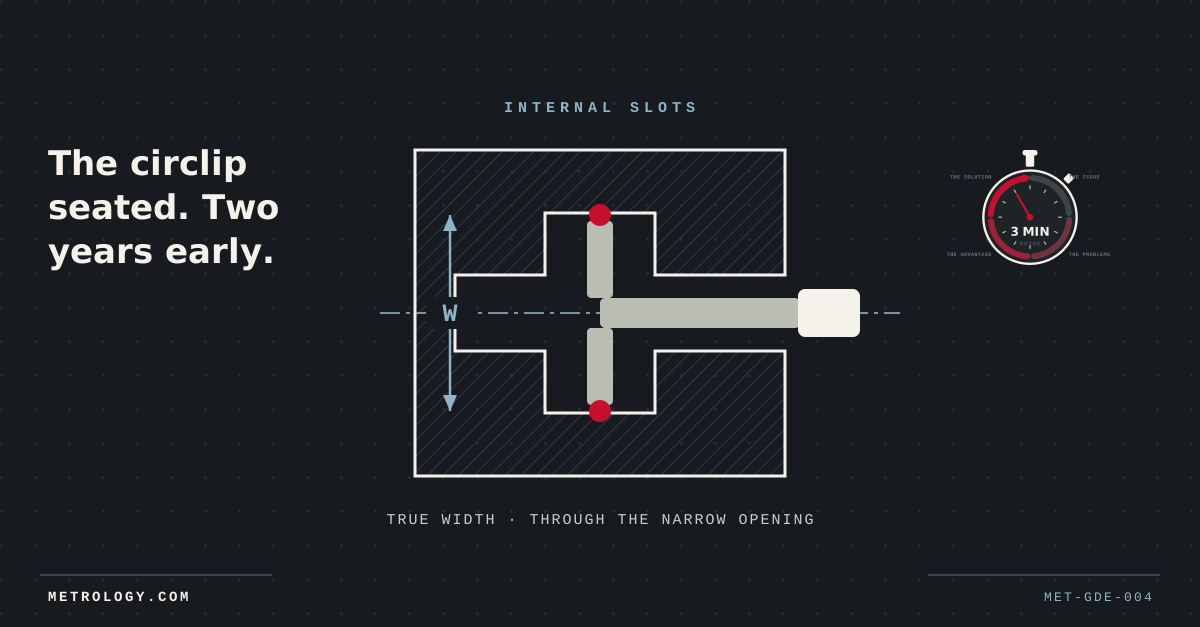
Internal slots break the founding assumption of bore gauging: that the feature is round. A circlip groove that isn't a full circle, a keyway broached inside a bore, a recess machined behind a smaller opening — these are width measurements hiding inside diameter-shaped access, and the
Internal slots break the founding assumption of bore gauging: that the feature is round. A circlip groove that isn't a full circle, a keyway broached inside a bore, a recess machined behind a smaller opening — these are width measurements hiding inside diameter-shaped access, and the geometry is often deliberately obstructive: the slot is wider than the entry that leads to it. A retaining ring that seats in a slot cut 0.1 mm (0.004") off nominal doesn't fail at inspection — it fails in service, two years later, as a warranty claim with a clean paper trail.
The problems with the usual answers
Calipers can't enter; their jaws are the wrong shape for the opening and the wrong reach for the recess. Pin gauges only bracket the answer — between go and no-go lies everything you actually wanted to know. Feel-based telescoping methods produce a different number per operator. And the common last resort — sectioning a sample part — destroys the evidence to obtain it: one honest number, one scrapped component, and nothing you can do at production rate. None of these yields the slot width as a repeatable, traceable value.
The three-point advantage
A slot-application head presents opposed anvils sized to pass through the entry width, which then locate on the slot faces and read true width directly on the indicator. The instrument presets against a calibrated master — for slots, typically a certified slip-gauge stack or purpose-made master rather than a ring — so every reading is a deviation from a traceable reference: repeatable to 0.002 mm (0.0001"), single-handed, in seconds, at the machine. Three slot families are catered for: plain slots, recess slots wider than their opening, and special-shape slots with contacts machined to the profile. Standard coverage 6–200 mm (0.236"–7.87"); specials from 2 to 500 mm (0.079"–19.69").
How to specify
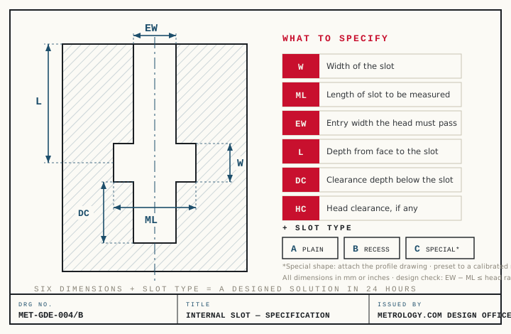
Six dimensions from your drawing decide the design — slot width (W), measured length (ML), entry width (EW), depth from face (L), clearance below the slot (DC), and head clearance (HC) — plus the slot type: plain, recess, or special (attach the profile drawing). The governing check is EW − ML against the head's measuring range — the single most common reason an off-the-shelf attempt at slot measurement fails, and the first thing our design office verifies on your drawing, before manufacture rather than after delivery. Send the drawing to the design office and a designed solution — head, anvils, master — comes back within 24 hours.
MET-BRF-001
Design Office
Send us the drawing.
A design engineer responds within 24 hours. No drawing yet? You can describe the part instead.