Spline Measurement - The Three Minute Metrology Guide
The issue
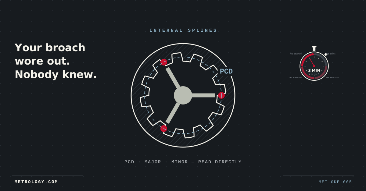
Ask what diameter an internal spline is and you've asked three questions. Major, minor and pitch circle diameter each govern a different aspect of fit — and the PCD, the one that controls load sharing and backlash, is a geometric construction no surface of the part physically
Ask what diameter an internal spline is and you've asked three questions. Major, minor and pitch circle diameter each govern a different aspect of fit — and the PCD, the one that controls load sharing and backlash, is a geometric construction no surface of the part physically presents. Meanwhile the tool that cuts the spline is wearing from its first stroke: PCD drift is the earliest warning a broach gives, and in most shops nobody is positioned to hear it until the scrap bin does.
The problems with the usual answers
Measurement between pins with calculation is accurate and slow — a bench exercise, not a production check, and error-prone on odd tooth counts where the pins don't sit opposite each other. Gear-checking machines and CMMs give the full answer at the cost of a queue: the part leaves the machine, the number arrives an hour later, and the broach keeps cutting in between. Plug-style spline gauges answer go/no-go only — no value, no trend, no warning. None of these puts the PCD, as a number, in an operator's hand at the spindle.
The three-point advantage
A spline-application head carries contacts machined to your tooth form — line or point contacts seating in the tooth spaces at the pitch line (the best-wire position) for PCD, line contacts for major diameter, extended contacts reaching the root for minor. Three-point contact self-centres in the spline, odd and even tooth counts each get their own contact arrangement, and the head presets against a calibrated setting ring so every reading is a deviation from a certified reference — repeatable to 0.002 mm (0.0001") in any operator's hands, in seconds, at the machine. If your drawing states a measurement-over-pins figure, the contacts are designed to reproduce that exact convention, so your gauge and your customer's calculation agree by construction. Standard coverage 6–200 mm (0.236"–7.87"); specials from 2 to 500 mm (0.079"–19.69").
How to specify
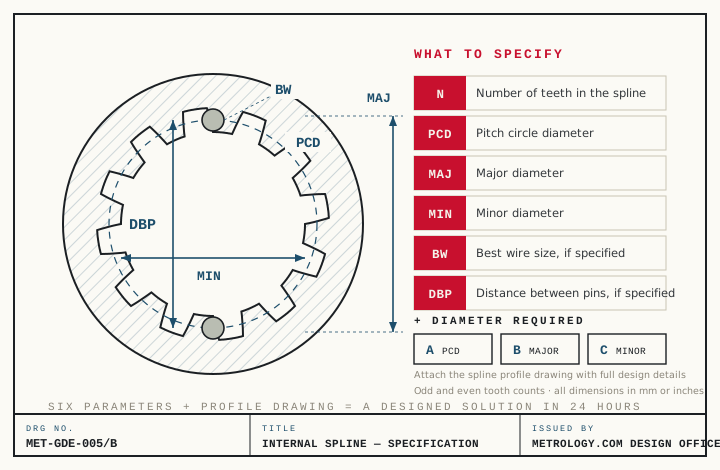
Send the spline profile drawing with full design details — it's the one application where the drawing isn't optional, because the contact geometry is machined to the tooth form. From it we take: number of teeth (N), pitch circle diameter (PCD), major (MAJ) and minor (MIN) diameters, and, if specified, best wire size (BW) and distance between pins (DBP) — plus which diameter or diameters you need to read. Odd counts, even counts, and combined-diameter heads on one handle are all standard design work. Send the profile drawing to the design office and a designed solution — head, contacts, setting ring — comes back within 24 hours.
MET-BRF-001
Design Office
Send us the drawing.
A design engineer responds within 24 hours. No drawing yet? You can describe the part instead.