Taper Measurement - The Three Minute Metrology Guide
The issue
A taper has a different diameter at every depth — which means "measure the bore" is an incomplete instruction. Any reading is meaningless without an answer to where: at what axial position, referenced from which face. Spindle noses, valve seats, hydraulic cones and tooling bores live or
A taper has a different diameter at every depth — which means "measure the bore" is an incomplete instruction. Any reading is meaningless without an answer to where: at what axial position, referenced from which face. Spindle noses, valve seats, hydraulic cones and tooling bores live or die on two numbers — the diameter at a defined datum, and the included angle — and a degree-minute of angle error at the spindle becomes runout at the tool tip, discovered in the cut rather than at inspection.
The problems with the usual answers
A conventional bore gauge will happily read a diameter in a taper — self-centring guarantees it reads somewhere — but without datum hardware, that somewhere shifts with operator technique, and two shifts of the same shop will "measure" different parts as identical. Taper plug gauges answer fit by bluing: informative, subjective, and numberless. A CMM answers everything, slowly, in another room. None of these gives diameter-at-datum and angle as repeatable shop-floor values, referenced the way the drawing references them.
The three-point advantage
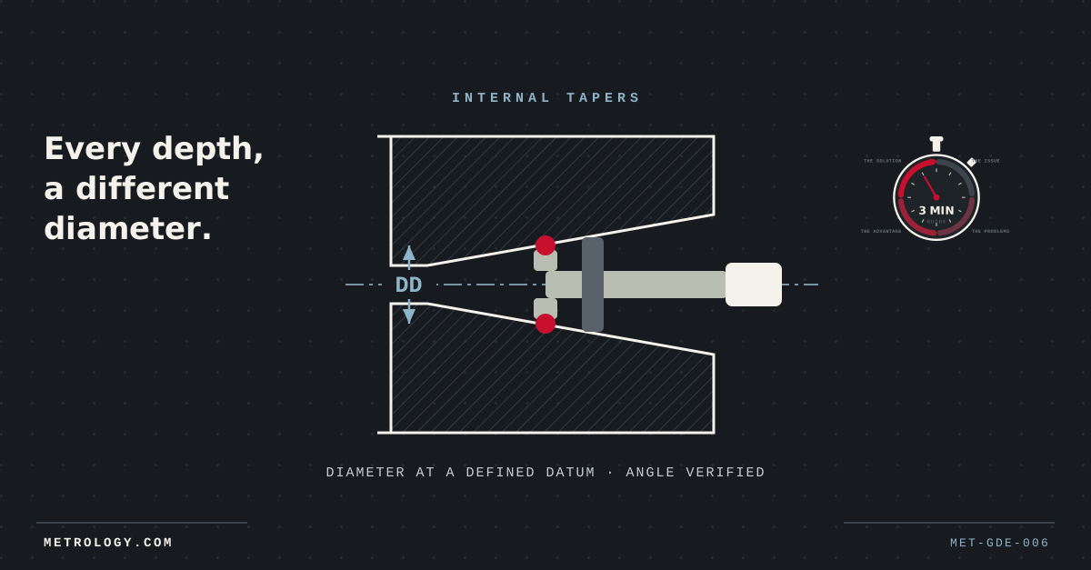
A taper-application head fixes the axial question mechanically: a clamp ring and calibrated C-washer locate the head at a defined datum position (LD) from the reference face, and the three-point contacts read the diameter (DD) at exactly that depth — repeatable to 0.002 mm (0.0001") in any operator's hands. Remove the C-washer of known thickness and re-seat, and the head reads at a second, precisely displaced position: from two diameters and a known displacement, the included angle follows directly — tan(θ) = (D1−D2)/2L1 — with the arithmetic on the design sheet, not left to the operator. Ball contacts are fitted at the datum for reliable seating on the inclined surface. The head presets against a calibrated setting ring; standard coverage 6–200 mm (0.236"–7.87"), specials from 2 to 500 mm (0.079"–19.69").
How to specify
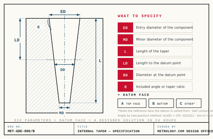
Six parameters from your drawing decide the design — entry diameter (ED), minor diameter (MD), taper length (L), datum position (LD), datum diameter (DD), and the included angle or taper ratio with its tolerance — plus the one detail that shapes the hardware: which reference face the datum is called from, because the clamp ring is dimensioned to your component, not adapted to it. Send the drawing to the design office and a designed solution — head, clamp ring, washers, arithmetic — comes back within 24 hours.
MET-BRF-001
Design Office
Send us the drawing.
A design engineer responds within 24 hours. No drawing yet? You can describe the part instead.