O Ring Measurement - The Three Minute Metrology Guide
The issue
An O-ring is only as good as the gland it sits in, and every sealing-failure investigation eventually arrives at the same unglamorous place: the groove. Its diameter — always larger than the bore that hides it — carries some of the tightest tolerances on the drawing, routinely ±0.
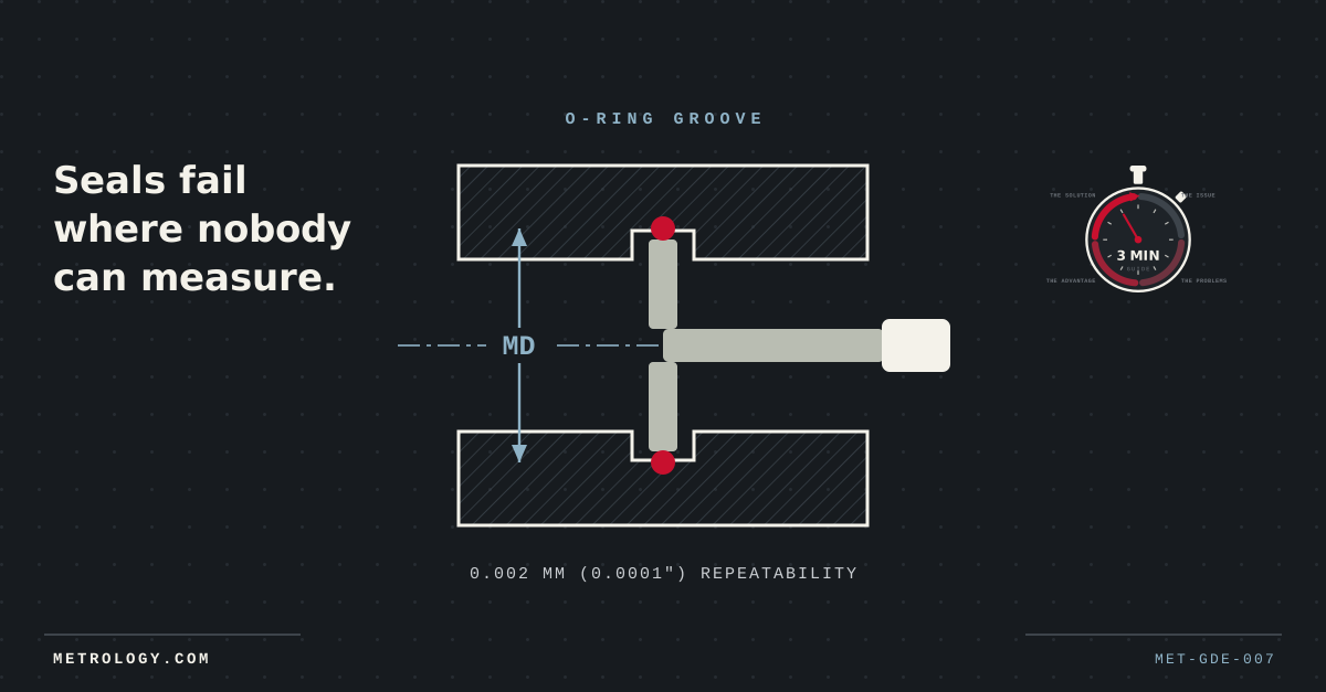
An O-ring is only as good as the gland it sits in, and every sealing-failure investigation eventually arrives at the same unglamorous place: the groove. Its diameter — always larger than the bore that hides it — carries some of the tightest tolerances on the drawing, routinely ±0.05 mm (±0.002") in aerospace and hydraulic work, on a surface nobody can see and most instruments cannot reach. The geometry is deliberately obstructive: the measured diameter (MD) sits behind a smaller entry bore (ED), exactly where a caliper's jaws and a standard bore gauge's anvils cannot go. Get it wrong and the consequences arrive later, in service: too shallow and the seal extrudes under pressure; too deep and compression is lost. Either way, the leak is diagnosed months after the part left inspection with a pass.
The problems with the usual answers
Telescoping and small-hole gauges depend entirely on operator feel — two inspectors, two answers, and no defensible number for the quality record. Moulded impression compounds add a casting step, its cure time, and its shrinkage to every reading, converting a dimensional measurement into a materials experiment. Sectioning a sample gives one accurate number and one destroyed part — acceptable for a failure investigation, useless for production control. A CMM with a star stylus can reach some grooves, but turns a ten-second shop-floor check into an inspection-room queue, and still struggles to establish the true diameter on a narrow radius-form groove where the stylus has almost nothing to land on. None of these belongs on a production line, and none produces the repeatable, traceable figure an auditor or a customer deviation request demands.
The three-point advantage
A purpose-designed groove head runs extended anvils sized to pass through the entry bore, which then locate outward into the groove and seat on its true diameter. Three carbide contacts at 120° self-centre in the groove — the reading is the diameter, not a chord, and not a feel-dependent estimate. The instrument presets against a calibrated setting ring, so every reading is a deviation from a certified reference, and the result appears directly on the indicator: single-handed, on the shop floor, in seconds, repeatable to 0.002 mm (0.0001") by any operator, with no special skill required. Square grooves, radius grooves and special profiles each take their own contact form, machined to your gland. Where the diameter alone isn't the whole story, the companion width system measures groove width, position from the face, and relative position between grooves — the full gland geometry, with no calculation asked of the operator. Standard-system coverage runs 6–200 mm (0.236"–7.87"), with specials engineered from 2 to 500 mm (0.079"–19.69").
How to specify
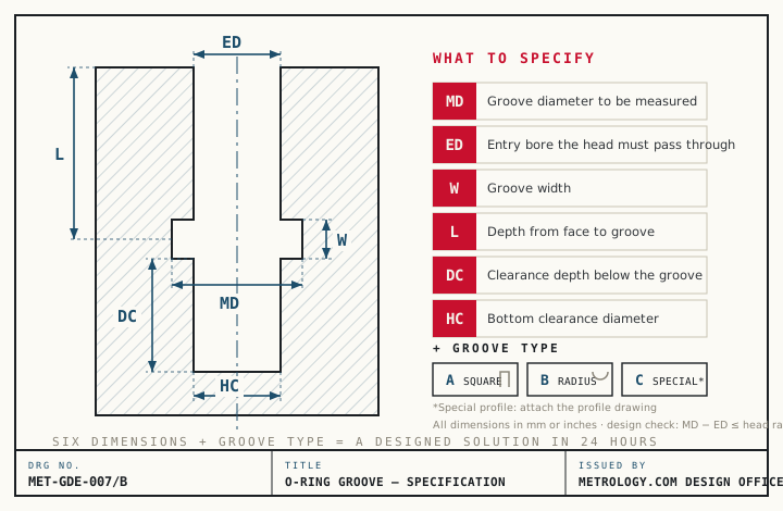
Five dimensions from your drawing decide the design — measured diameter (MD), entry diameter (ED), groove width (W), depth to the groove (L), and the clearances around it (DC, HC) — plus the groove type: square, radius, or special profile (attach the profile drawing). The governing check is MD − ED against the head's measuring range; our design office verifies it before anything is made, so the limitation is engineered out on paper rather than discovered in the inspection room.
MET-BRF-001
Design Office
Send us the drawing.
A design engineer responds within 24 hours. No drawing yet? You can describe the part instead.